Robo Roach Part 1

Input Devices Project
Overview
For this week's Input Devices assignment, I started building a small photophobic robot cockroach called RoboRoach. The idea came from my 6.200 Circuits & Electronics class, where we built a purely analog light-following robot using phototransistor. I thought it would be fun to flip the behavior and make something that runs away from light instead, just like a real cockroach. Additionally, to meet the requirements of the assigment, I'd also need to add a microcontoller. For this week, I will just use it to read the output data from the op-amps. But, for the output devices week, I will program it to dictate the behaviour logic of the RoboRoach. I experimented with photosensors and op-amps to create and amplify light-dependent voltages, as well as the ESP32C3 to read op-amp outputs. This week was all about learning how to treat these components as input devices and measuring the voltages they produce. I will build on this project during next week's assignment to complete my photophobic RoboRoach
Board Design
For RoboRoach, my goal is to turn light intensity into an analog signal that becomes greater in magnitude as the robot is exposed to brighter light to mimick a cockroach trying to escape illumination.
To do this, I used a phototransistor as a light sensor, an op-amp amplifier, and an MCU to read the output voltages from the op-amps.
The phototransistor is placed in a voltage divider so that it produces a larger current as light intensite increases, which causes an increase in the voltage drop across the resistor that is in series with it.
That raw signal is very small, so I added an op-amp gain stage to amplify the voltage from the light sensor into something the system can actually react to.
The final output from the op-amp goes to the MCU so I can read it on my computer and eventually process it to dictate the behaviour of the robot.
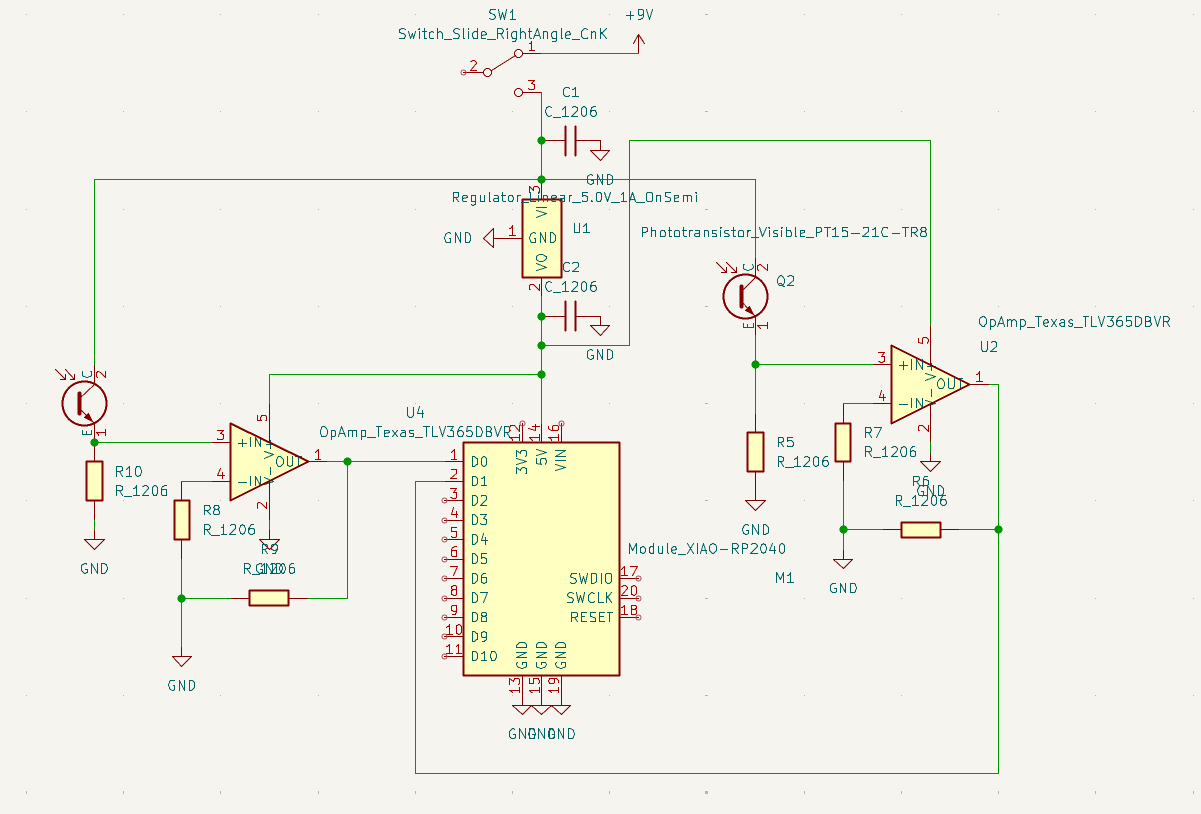
The hand-drawn schematic below shows the main blocks of the circuit: the phototransistor voltage divider, the gain stage, and the mcu.

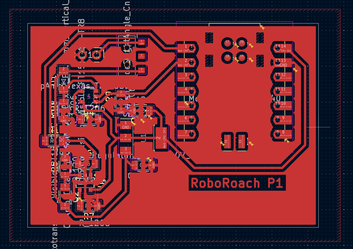
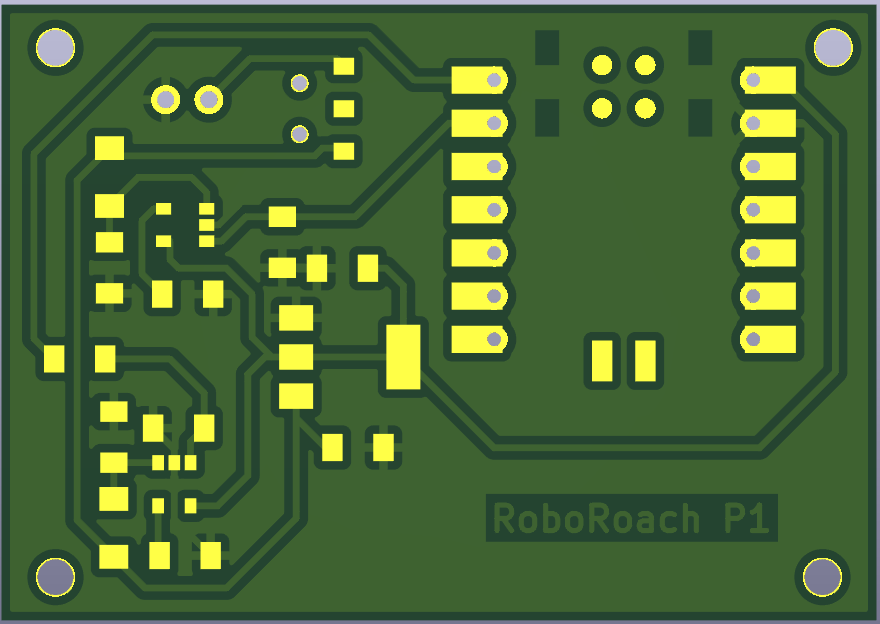
I also created the schematic and layout in KiCad that I used for milling and assembly.
Milling
For milling this board, I followed the exact same workflow as in my Electronics Production week. I reused the same design rules and trace widths from my previous boards, exported the traces and outline as PNGs, and ran them through Mods on the Roland mill.
Gerber File

PNG


MODs
I used a 1/64" bit for traces and a 1/32" bit for drilling and outline.
Once the board finished milling, I did a quick pre-solder continuity check using the multimeter in continuity mode just to make sure there were no accidental shorts from the mill.
- Touch the probes to two traces that should NOT be connected → it should NOT beep.
- Touch two ends of the same trace that should be connected → it should beep.
This catches milling shorts, broken traces and copper that didn't fully mill away
Soldering
I similarly followed the soldering workflow from my Electronics Production week. For this board, I only had to place the op-amp, the potentiometer, a few resistors, and the ESP32C3 for the divider and offset network. I started with the op-amp and mcu by tinning one pad, placing the chip with tweezers, and reflowing that pin to hold it down. After that, I soldered the rest of the pins for each of these and then added the resistors and potentiometer. Nothing on this board was especially tricky, so I mostly just followed the usual steps and soldered everything in place. After assembling the board, I used a multimeter in continuity mode to check that I didn't accidentally bridge any pins and that each part was actually connected to its trace. Once that was done, the board was ready for testing.
Testing
To test this board, I programmed an ESP32-C3 in the Arduino IDE and used it to read the two op-amp outputs.
Each amplified phototransistor signal was connected to one of the MCU's ADC pins, and I printed the readings to the serial monitor while I adjusted the lighting.
Shining a flashlight on either sensor or covering it confirmed that both channels responded correctly and independently to changes in light intensity.

Download code here.
See finished RoboRoach in Output Devices